Poor designs have a compound effect. And it doesn’t matter if you order parts once or repeatedly, it impacts your bottom line. That’s why optimizing your sheet metal designs is vitally important.
As a sheet metal fabricator, we see a LOT of drawings from OEMs. While some have good tolerances and follow sound Design for Manufacturability (DFM) practices. Many have arbitrary or unrealistic tolerances, or strictly use default tolerances, which increases costs and adds needless complexity to the whole manufacturing process.
In this TriparTech guide, we cover the 10 dos and dont’s for optimizing your sheet metal designs using proven Design for Manufacturability (DFM) principles. Ignoring them is costing you money. Let’s fix that now.
1. DON’T arbitrarily apply default tolerance tables
This is a basic mistake we see in many drawing templates. For example, in Figure 1a, most features of your part do not require such tight tolerances, change the table as shown in Figure 1b.
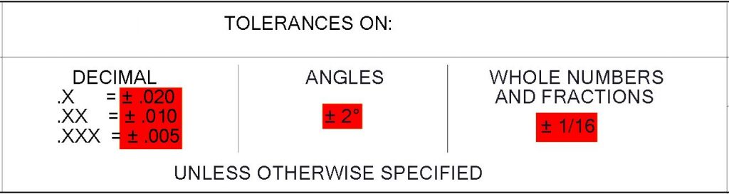
Figure 1a: Default Tolerances
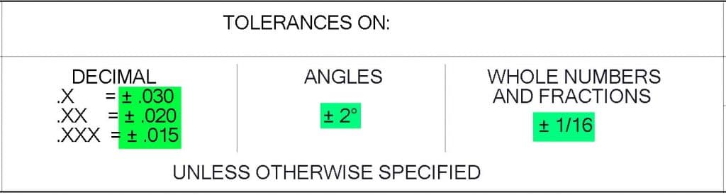
Figure 1b: Revised Tolerances
There may be times where you must tighten default tolerances for stringent applications. If this is required, so be it, but remember that this often drives up costs. Don’t worry if your drawings do not all contain the same default tolerance table. It is up to the manufacturer to read and respect these and all requirements noted.
2. DON’T forget about default angular tolerance in the same table
These often state ANGLES ± 1/2⁰ (or ± 30’). This translates to only 0.009” over a 1”! If your part only needs ± 1⁰ or ±2⁰, be sure to change it. As noted above, any tolerance tighter than necessary is a potential cost driver.
3. DON’T blindly rely on the default tolerance table
Besides specifying tolerance based on the number of decimal places, the same table almost always states UNLESS OTHERWISE SPECIFIED. Even if you have modified your default tolerance table (as suggested in points 1 & 2), there may be features that can afford greater tolerances (that may also be potential cost drivers).
If so, override (OTHERWISE SPECIFY) the default tolerance by adding the more relaxed tolerance right after the dimension. Figure 2a below shows a dimension of 2.875, which in the case of the associated default tolerance table, would carry a tolerance of ± .005”. If in fact this is not only tighter than necessary, but say that it can also never be below 2.875, override the default tolerance by adding only what is required; e.g. the same 2.875 dimension, but with a wider +.03/-.00 tolerance, if that is what the part and eventually assembly require.
4. DON’T dimension to theoretical points
For example, 4.21. Instead, try to dimension to physical features that are easily measured on the part.

Figure 3a

Figure 3b
5. DON’T dimension to features that are not in line with one another
For example Figure 4a shows the relative position of two knockout holes. Being offset in both directions can make it difficult on the factory floor for the fabricator to check this. Considering that the relative position of two adjacent knockouts is rarely critical, an simpler dimensioning scheme is shown in Figure 4b below, where the position of both holes is independent and referenced from edge that are adjacent to both.

Figure 4a: Relative dimensioning

Figure 4b: Independent dimensioning
6. DON’T specify perfect flatness
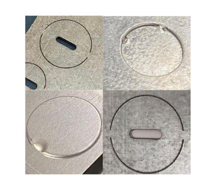
The truth is: nothing is ever perfectly flat. So avoid asking for cost-driving near impossible perfection. Instead, try to bias your flatness tolerance by allowing a degree of curvature in one direction, so that the part will flatten upon assembly or even become a feature. For example, the driver box cover shown below are intentionally curved so that once the tab at one end is placed into a receiving slot in the box, the cover will “unroll” or flatten itself until the free end is snapped and held by a retaining spring.
This ensures the cover makes intimate contact with the top edges of the box. Installed the opposite way would leave a bowed cover and a wide gap in the middle. With a smart design, this however is impossible as the tab at the end is off-center, forcing it to be oriented prior to installation, with the curvature in the intended direction.

Figure 5: Curved cover flattening upon installation
7. DO consider bend complexity
Every bend adds complexity, and a dimension & tolerance that is dependent on the precision of two or more bends, becomes increasingly difficult to achieve. Managing tolerances and dimensions over multiple bends is vital for optimal precision.
For example, figure 6a below shows a somewhat tall yoke (U-shaped) bracket with an inside dimension and tolerance of 5” ± .06”, (which as dimensioned, applies over the entire height of the part). The ± .06 tolerance may seem generous, but over a 10” height, if the bottom is at the lower limit of this (4.94”), and the top end at the upper limit (5.06”), that results in an angular difference per side of only 0.3⁰!
Instead, think about your specific application. Often the upper, or “free” ends of the yoke is intended to secure something that fits or is secured within it, at which point the arms should appear to be nearly parallel.

Figure 6a: Arbitrary dimension & tolerance applied over full height of yoke

Figure 6b: Tight tolerance applied to bend area, with generous tolerance to arms
A way to achieve this at lower cost is shown in Figure 6b, which specifies that the 5” ± .06” dimension only applies where the radius at the closed end finishes, but that the free end may be more generous at 5” ± 0.25”. Sure, the arms may appear dreadfully non-parallel upon receipt from the fabricator, but have a better chance of being within a far more cost-effective tolerance, yet when assembled with whatever fits within the free ends, will end up being parallel! If you want the part that fit within the arms to always have light to moderate pressure, bias the tolerance, while still keeping it generous, e.g. 4.98” +0.00/-.25”.
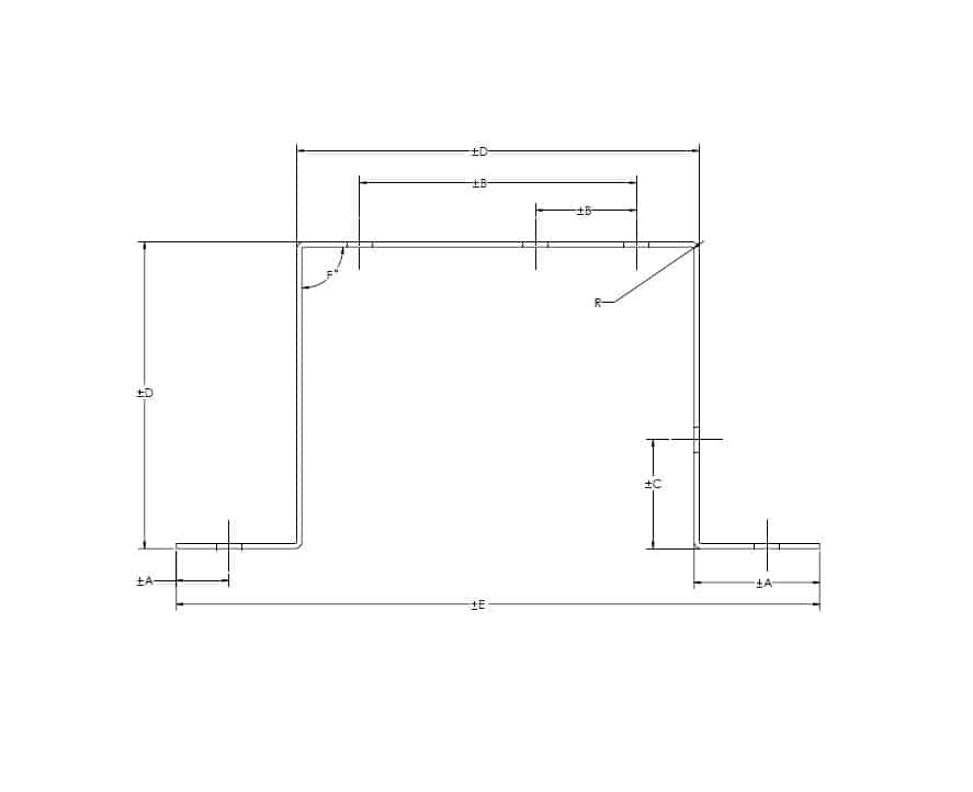
Now imagine a similar yoke, but one which has two more bends as shown in Figure 7a. Here, the upper or “free” end dimension of the yoke is determined by four bends. Achieving a tight tolerance in this case is even more difficult to achieve, and even more costly if an arbitrary tolerance is given without thought to the manufacturing difficulties involved. Apply the same strategy as explained above to keep costs down without compromising your overall assembly.

Figure 7a: Tight dimension & tolerance applied only to the free end opening

Figure 7b: Where possible, tighter tolerance applied to bend areas, with no tolerance to the free end opening
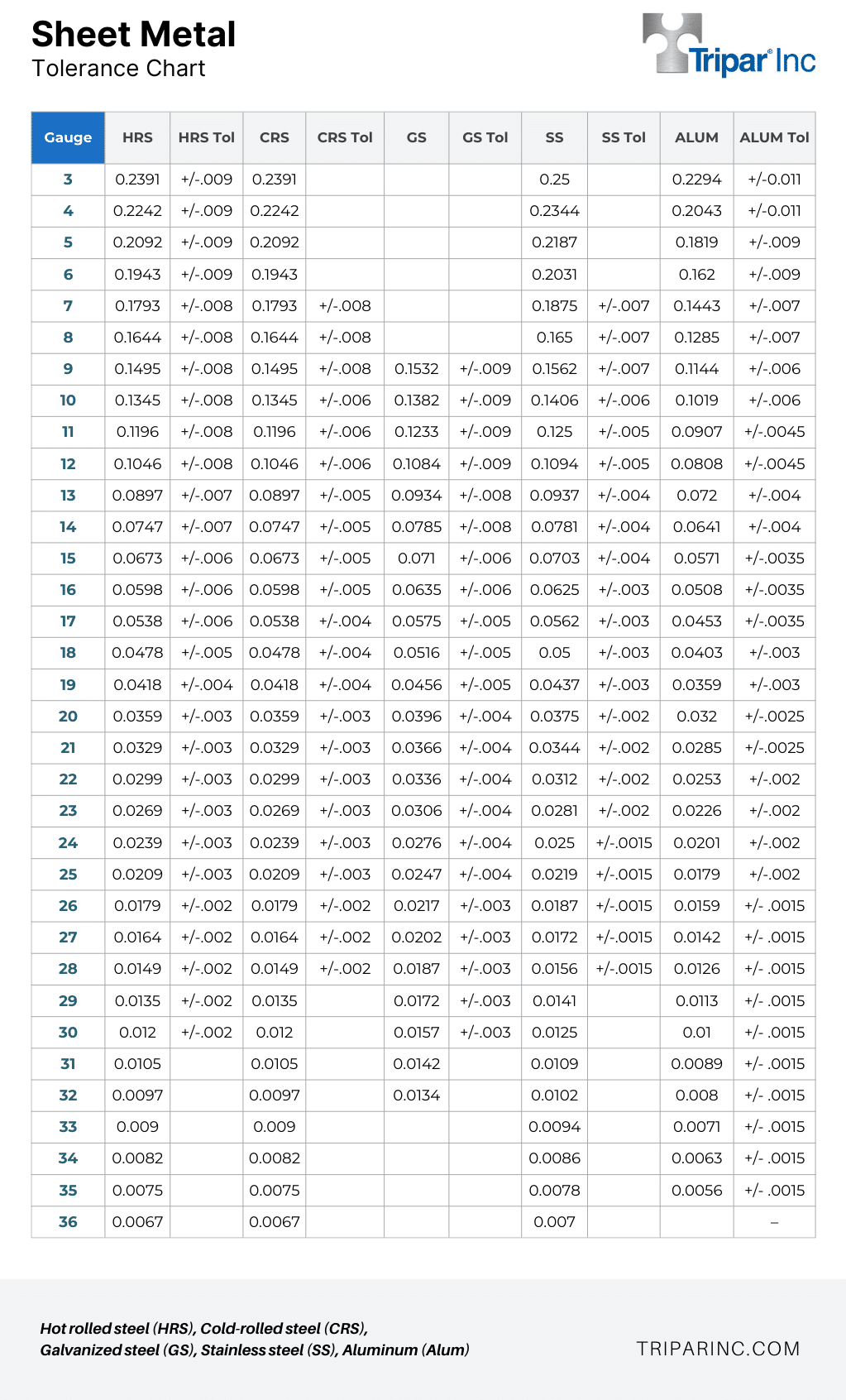
8. DO account for material thickness tolerances
Every material comes with its own inherent thickness tolerances. Failing to account for these subtle variations in your sheet metal designs can lead to costly dimensional inaccuracies and assembly issues.
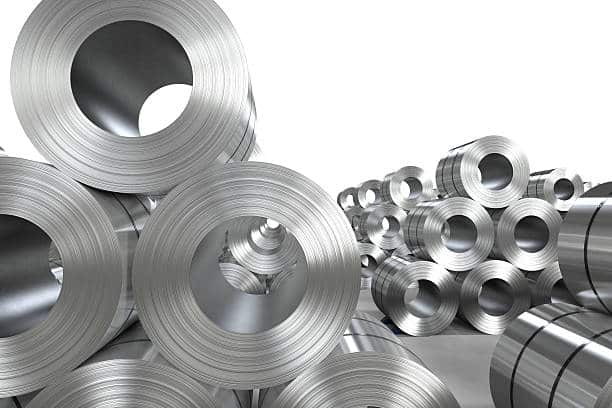
For example, cold-rolled steel (CRS) and galvanized steel may be offered in the same gauges, but they both come with different tolerances. Similarly, some materials are not bought in gauges, but in nominal thicknesses (e.g. aluminum and stainless steel). So make sure that your designs, drawings, and tolerances line up with these material tolerance variations.
Sheet Metal Tolerance Table
9. DO design for inside dimensions
Remember that when sheet metal parts are bent or formed, they are usually “wrapped” around a male die. Therefore, dimensions should be to the inside of such radii or forms, as the outside isn’t as controllable, and also affected by the material thickness tolerance or variations.
10. DO be flexible is specifying bending radiis
By providing flexibility in bending radiis, you maximize the chances that your fabricator can use existing tooling; saving you from the hidden and expensive upfront costs of custom dies. So provide latitude where possible.
For example, if you are designing with 16 GA CRS (0.06”), and have called for an inside radius of 0.12 (smartly adhering to the rule of thumb that inside radii should never be less than 1.5 times material thickness, or preferably 2 times the material thickness), but you can live with an inside radii up to 0.18”, specify the radii as 0.18/0.12”.
This increases the chances that your fabricator will have existing dies within the range. Don’t worry if your flat development was designed for a 0.12” radius. If your fabricator wishes to use a 0.18” radius, it is up to them to modify the flat development to yield the bent part. After all, what you are purchasing is generally the bent or formed part, which is what your supplier must respect.
10. BONUS: DO know that deburring increases cost
Understand that any sheet metal parts (metal stamped or CNC fabricated), by its very nature, will have some slightly sharp edges and small burrs. Specifying “PARTS SHALL BE FREE OF BURRS”, or worse “DEBURR AND BREAK ALL SHARP EDGES”, will drive up your costs.
Having small burrs is normal. That is why sheet metal fabricators will often state on their quote “PART SUPPLIED IN ITS AS STAMPED CONDITION.” If this is an issue, it’s up to the OEM to discuss it with their suppliers.
If this is an absolutely required, there are ways it can achieved, but at increased cost. Small parts not subject to permanent distortion from light loads may be able to be tumbled or vibratory finished. This may soften the outer edges of the part, but depending on the deburring process and media used, it may not deburr within tight corners or small holes & cut-outs. Larger and more fragile parts may need to be run through a timesaver (part passed through a sandwich of two wide flat abrasive belts), or hand manipulated to deburr edges against an abrasive belt or wheel. However, all these are extra steps, adds cost, and may affect or change the surface finish in unpredictable and often non-repeatable ways.
In conclusion
Remember that relying on a drawing’s default tolerances may save you design time but if the results are over-tolerance (or ill-tolerance) parts, it may not work within your assembly. And while you may experience initial savings in reduced design time, it can easily be wiped out by recurring part costs, for which there may be 1000s, 10,000s, or 100,000s produced over many years.
Think about how your parts will ultimately be used, dimensioning and tolerancing appropriately. Remember that large tolerances do NOT equate to low quality. In fact, a well dimensioned properly toleranced part equates to quality as it yields the part you need for the application; no more and no less, while having the greatest potential to save on unit costs.
Finally, you, the OEM, knows how each part is used in your assembly, thus you’re in the best position to give time and consideration to tolerancing. If you’re unsure, share your assembly with a trusted fabricator. If they are any good, they will spot the cost drivers immediately and will advise you to make the appropriate changes.